Tuesday, 5 November 2013

Configuring the Cisco Router and VPN Clients Using PPTP and MPPE

Components Used

The information in this document is based on the software and hardware versions:
  • Cisco 2621 Router that runs Cisco IOS Software Release 12.2
  • Microsoft Windows 2000
The information in this document was created from the devices in a specific lab environment. All of the devices used in this document started with a cleared (default) configuration. If your network is live, make sure that you understand the potential impact of any command.

Network Diagram

This document uses this network setup:
pptp-ios-1.gif

Conventions

Refer to Cisco Technical Tips Conventions for more information on document conventions.

PPTP Router Configuration

These IOS commands are applicable to all platforms that support PPTP.
2621#configure terminal
Enter configuration commands, one per line.  End with CNTL/Z.

!--- Enable virtual private dial-up networking.


2621(config)#vpdn enable

!--- Enters VPDN group configuration mode for the specified VPDN group.


2621(config)#vpdn-group 1

!--- Enters VPDN accept-dialin configuration mode 
!--- and enables the router to accept dial-in requests.

2621(config-vpdn)#accept-dialin

!--- Specifies which PPTP protocol is used.

2621(config-vpdn-acc-in)#protocol pptp

!--- Specifies the virtual template that is used 
!--- in order to clone the virtual access interface.

2621(config-vpdn-acc-in)#virtual-template 1
2621(config-vpdn-acc-in)#exit

2621(config)#ip local pool test 192.168.1.1 192.168.1.250

!--- Create virtual-template interface used for cloning
!--- virtual-access interfaces with the use of address pool test
!--- with Challenge Authentication Protocol (CHAP) authentication, PAP, and MS-CHAP.

2621(config)#interface virtual-template 1

2621(config-if)#encapsulation ppp
2621(config-if)#peer default ip address pool test
2621(config-if)#ip unnumbered FastEthernet0/0
2621(config-if)#no keepalive
2621(config-if)#ppp encrypt mppe auto
2621(config-if)#ppp authentication pap chap ms-chap

Monday, 26 August 2013

How to Configure Static NAT for Inbound Connections?

Someone recently asked me how to configure Network Address Translation (NAT) so that computers on the Internet could access his internal Web and mail server through his Cisco router. This requires configuring a static NAT translation between the dedicated public IP address and the dedicated private IP address. Here’s how to do it.
Most people use NAT to connect to the Internet these days. NAT transforms private IP addresses to public IP address so users can access the public Internet. Most of us use a form of NAT calledPort Address Translation (PAT), which Cisco refers to as NAT overload. (For more information, see How to Set up NAT using the Cisco IOS and How to Set up PAT (Port Address Translation) in the Cisco IOS.”)
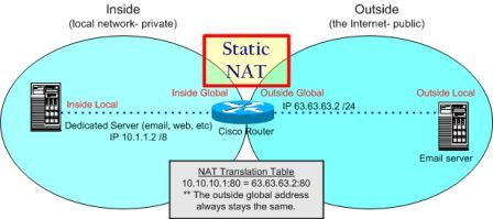
To start off, let’s get a better idea of what we’re working with. Figure A offers a diagram to help visualize the network.
How to Configure Static NAT for Inbound Connections
Here’s our goal: We want to configure a static IP translation through the router from the outside (i.e., Internet) network to the inside (i.e., private) network.
On a Linksys router with a basic Web interface, this isn’t very hard to do. However, on a Cisco router using the command-line interface (CLI), you’ll struggle if you don’t know the proper commands or where to apply them.
It’s a good idea to gather the data you’ll need before you start. Here’s the information we need for our example:
  • Router inside interface E0/0: IP 10.1.1.1
  • Router outside interface S0/0: IP 63.63.63.1
  • Web/mail server private IP: 10.1.1.2
  • Web/mail server public IP: 63.63.63.2
There are two important steps to get this traffic inside your network and to your Web/mail server:
  1. NAT configuration
  2. Firewall configuration
In this post, I’ll provide the basic static NAT configuration. However, make sure that whatever you’re using for your firewall also allows this traffic in.
Whether you’re using basic Access Control Lists (ACLs) or the Cisco IOS firewall feature set, make sure you understand the Cisco IOS order of operations to configure your firewall for the right IP addresses (public or private). In other words, what happens first — NAT translation or firewall filtering? For example, when using ACLs, a check of the input ACL occurs before NAT translation. So, you need to write ACLs with the public IP addresses in mind.
Now that we’ve covered the background info, let’s get started with configuring static NAT. For our example, let’s say we start out with this basic configuration:
interface Serial0/0
ip address 63.63.63.1 255.255.255.0
ip nat outside
interface Ethernet0/0
ip address 10.1.1.1 255.255.255.0
ip nat inside
We need the NAT translations to translate the outside IP address of the Web/mail server from63.63.63.2 to 10.1.1.2 (and from 10.1.1.2 to 63.63.63.2). Here’s the missing link between the outside and inside NAT configurations:
router (config)# ip nat inside source static tcp 10.1.1.2 25 63.63.63.2 25
router (config)# ip nat inside source static tcp 10.1.1.2 443 63.63.63.2 443
router (config)# ip nat inside source static tcp 10.1.1.2 80 63.63.63.2 80
router (config)# ip nat inside source static tcp 10.1.1.2 110 63.63.63.2 110
We used the above port numbers because they fit the description of what we wanted to do, but keep in mind that your port numbers may be different. I chose port 25 for SMTP (sending mail), port 443 for HTTPS (secure Web), port 80 for HTTP (Web traffic), and port 110 for POP3 (receiving mail from the mail server when out on the Internet).
This configuration assumes you have a block of IP addresses. If you don’t, you can use the outside IP address on your router (Serial 0/0 in our case), and you could configure it like this:
router (config)# ip nat inside source static tcp 10.1.1.2 25 interface serial 0/0 25
You can even use this command if you have a dynamic DHCP IP address from your ISP on the outside of your router.
We also need to register the IP address of the mail and Web server in the global Internet DNS registry. So when users enter www.mywebserver.com in their Web browser, the browser would translate it to 63.63.63.2, and the router would then translate it to 10.1.1.2. The Web server would receive that request and respond back through the router, which would translate it back to the global IP address.
In addition to configuring static NAT, you may want to use dynamic NAT at the same time. With this, your inside PCs could access the Internet using dynamic NAT (i.e., NAT overload or PAT). But this gets a little more complex. For more information, see Cisco’s Configuring Static and Dynamic NAT Simultaneously documentation.

How to Configure Basic NAT with Overloading?

Here’s a lab that might be helpful for those working towards the CCNA examination.
We have a simple topology consisting of three routers. R8 will simply be used as a host on our “internal” network and R7 will be used as our border router (the serial connection between R5 and R7 will represent our connection to the Internet):
The goal is to NAT any traffic originating on our internal network (R8) as it leaves the serial 0/0 interface on R7 on its way to the “Internet” (R5). Overloading (having multiple clients all NAT’d to the same IP address) is probably the most common implementation (especially for those of us who run NAT on a Cisco box at home!).
Configuring Basic NAT with Overloading
Let’s get basic connectivity working first:
R5# configure terminal
R5(config)# interface serial 0/0
R5(config-if)# ip address 172.16.57.5 255.255.255.0
R5(config-if)# no shutdown

R7# configure terminal
R7(config)# interface serial 0/0
R7(config-if)# ip address 172.16.57.7 255.255.255.0
R7(config-if)# no shutdown
R7(config-if)# interface fastethernet 0/1
R7(config-if)# ip address 172.16.78.7 255.255.255.0
R7(config-if)# no shutdown

R8# configure terminal
R8(config)# no ip routing
R8(config)# interface fastethernet 0/1
R8(config-if)# ip address 172.16.78.8 255.255.255.0
R8(config-if)# no shutdown
R8(config-if)# ip default-gateway 172.16.78.7
On R7, let’s verify we can ping both R5 and R8:
R7(config-if)# do ping 172.16.57.5
Type escape sequence to abort.
Sending 5, 100-byte ICMP Echos to 172.16.57.5, timeout is 2 seconds:
!!!!!
Success rate is 100 percent (5/5), round-trip min/avg/max = 1/3/4 ms
R7(config-if)# do ping 172.16.78.8
Type escape sequence to abort.
Sending 5, 100-byte ICMP Echos to 172.16.78.8, timeout is 2 seconds:
..!!!
Success rate is 60 percent (3/5), round-trip min/avg/max = 1/2/4 ms
Alright, looks good. Now we can start with configuring NAT. First, let’s define our NAT inside and NAT outside interfaces (fastethernet 0/1 and serial 0/0, respectively):
R7(config-if)# interface fastethernet 0/1
R7(config-if)# ip nat inside
R7(config-if)# interface serial 0/0
R7(config-if)# ip nat outside
Next, we need to create an access-list to match the “internal” IP addresses (the ones we want to be NAT’d). In this case, our internal network is 172.168.78.0/24. Our ACL to match that network is simple:
R7(config-if)# ip access-list standard NAT
R7(config-std-nacl)# permit 172.16.78.0 0.0.0.255
Last, we’ll use the “ip nat …” command to actually instruct the router on what we want to NAT:
R7(config)# ip nat inside source list NAT interface serial 0/0 overload
This tells IOS that any packets coming in the “inside” interface (fastethernet 0/1) that are permitted by the named access-list “NAT” will have their “source” address translated to the IP address assigned to “interface serial 0/0″. In addition, NAT translations will be overloaded — that allows multiple devices inside to be translated to the same IP address.
To verify that NAT is working properly, let’s start a “debug ip icmp” on R5. Then, we’ll attempt to ping R5 from R8 and see what happens:
R5# debug ip icmp
ICMP packet debugging is on
R8(config)# do ping 172.16.57.5 
Type escape sequence to abort.
Sending 5, 100-byte ICMP Echos to 172.16.57.5, timeout is 2 seconds:
!!!!!
Success rate is 100 percent (5/5), round-trip min/avg/max = 4/4/8 ms
We see that our pings were successful. What did R5 see?
R5# debug ip icmp
ICMP packet debugging is on
R5#
*Mar  1 19:07:25.603: ICMP: echo reply sent, src 172.16.57.5, dst 172.16.57.7
*Mar  1 19:07:25.611: ICMP: echo reply sent, src 172.16.57.5, dst 172.16.57.7
*Mar  1 19:07:25.615: ICMP: echo reply sent, src 172.16.57.5, dst 172.16.57.7
*Mar  1 19:07:25.619: ICMP: echo reply sent, src 172.16.57.5, dst 172.16.57.7
*Mar  1 19:07:25.623: ICMP: echo reply sent, src 172.16.57.5, dst 172.16.57.7
So R5 saw the echo requests and sent echo replies back, but notice the IP addresses. The source IP address of the echo replies is 172.16.57.5 (R5), but the destination IP address is 172.16.57.7 (R7). We can be sure that NAT is working, in part because R5 does not have a valid route to R8′s “real” IP address, 172.16.78.8:
R5# show ip route | begin Gateway
Gateway of last resort is not set
     172.16.0.0/24 is subnetted, 1 subnets
C       172.16.57.0 is directly connected, Serial0/0
R5# ping 172.16.78.8
Type escape sequence to abort.
Sending 5, 100-byte ICMP Echos to 172.16.78.8, timeout is 2 seconds:
…..
Success rate is 0 percent (0/5)
Be sure to check out the NAT translation table on R7, which should show a valid translation for the ICMP traffic that originated at R8:
R7(config)# do show ip nat translations
Pro Inside global      Inside local       Outside local      Outside global
icmp 172.16.57.7:0     172.16.78.8:0      172.16.57.5:0      172.16.57.5:0
Finally, we can use “debug ip nat” on R7 to see what’s happening there. Let’s turn that on, then ping R5 from R8 again:
R7# debug ip nat
IP NAT debugging is on
R8(config)# do ping 172.16.57.5
Type escape sequence to abort.
Sending 5, 100-byte ICMP Echos to 172.16.57.5, timeout is 2 seconds:
!!!!!
Success rate is 100 percent (5/5), round-trip min/avg/max = 4/4/8 ms
And what do we see on R7?
R7#
*Mar  1 19:15:13.695: NAT: s=172.16.78.8->172.16.57.7, d=172.16.57.5 [5]
*Mar  1 19:15:13.699: NAT*: s=172.16.57.5, d=172.16.57.7->172.16.78.8 [5]
*Mar  1 19:15:13.703: NAT*: s=172.16.78.8->172.16.57.7, d=172.16.57.5 [6]
*Mar  1 19:15:13.707: NAT*: s=172.16.57.5, d=172.16.57.7->172.16.78.8 [6]
*Mar  1 19:15:13.707: NAT*: s=172.16.78.8->172.16.57.7, d=172.16.57.5 [7]
*Mar  1 19:15:13.711: NAT*: s=172.16.57.5, d=172.16.57.7->172.16.78.8 [7]
*Mar  1 19:15:13.715: NAT*: s=172.16.78.8->172.16.57.7, d=172.16.57.5 [8]
*Mar  1 19:15:13.715: NAT*: s=172.16.57.5, d=172.16.57.7->172.16.78.8 [8]
*Mar  1 19:15:13.719: NAT*: s=172.16.78.8->172.16.57.7, d=172.16.57.5 [9]
R7#
*Mar  1 19:15:13.723: NAT*: s=172.16.57.5, d=172.16.57.7->172.16.78.8 [9]
R7#
We can see that the source IP address 172.16.78.8 (R8) is being translated to 172.16.57.7 (R7′s serial 0/0 interface). Success!

Cisco IOS Versions and Naming Overview

One thing that is often confusing to any network engineer (regardless of level) is the version and naming structure used by Cisco for their IOS images. Although the naming used for some of the newer devices is changing to a simpler structure, it will be a while before all the different versions are consolidated. This article covers these different releases and aims to give a single location where network engineers can look to figure out what the different releases mean. Although this is not an exhaustive list of every Cisco version, it does cover the most commonly used versions. 
Cisco IOS Releases
One term that is often used is the IOS release type. With versions of IOS earlier than 15, a specific image could be considered one of the following four different release types:
Early Deployment (ED): These releases provide both new features and new platform support in addition to bug fixes.
Limited Deployment (LD): These releases do not include any new features or platform support but do include bug fixes. LD releases are between an ED release and a GD release.
General Deployment (GD): These releases can be used anywhere in a customer network with the same feature and functionality requirements. These tend to be stable on almost all platforms.
Maintenance Deployment (MD): These releases are used to provide additional support for bug fixes and ongoing software maintenance.
With IOS 15 and later, both the LD and GD deployments will be retired. New releases will be considered either ED or MD. The IOS train paths have also been consolidated. With earlier versions of IOS, the different ED (T trains; for instance, 12.4T) and MD (not T trains; for instance, 12.4) has different code bases. With IOS 15 and later, the code bases will be consolidated. MD releases (called M releases, or extended release) will be released and have a 44-month support window, whereas ED (T releases, or standard release) will have a 18-month support window.
IOS Versions
A number of different versions exist within each release of IOS. This article takes a look at a few of these and how what they are used for.
IOS Version 12
With IOS Version 12, many different sub-versions of IOS exist, including specialized support for specific platforms; the next few sections cover a couple of the most common.
IOS Version 12 has a few different ways to notate version, including those shown in Figure1.
IOS Version 12 Version Notation
12
The 12 base versions are also referred to as the mainline release of a version. These releases tend to be the most stable and include support for most of the available platforms. Other more specialized versions of IOS are rolled into the mainline as an update when they have been sufficiently tested. (They go through the release process shown in the previous section.)
12T
The T train is used to add the newest features and platforms. After the software has been tested thoroughly, it is rolled into the mainline release.
12S, 12SB, 12SR
Many different IOS versions provide support for specific platforms. The ones shown in the section name are an incomplete list but do show some of the common examples. The 12S, 12SB, and 12SR versions tend to provide support for Cisco’s 7200, 7300, 7400, 7500, and 10000 platforms.
IOS Version 15
The way that different versions are referenced with IOS Version 15 is similar to that of IOS Version 12.
IOS Version 15 has a notation that is similar to IOS Version 12 and is shown in Figure2.
IOS Version 15 Version Notation
IOS Version 15M
As with IOS version 12, IOS Version 15M provides a mainline release and is also referred to as a maintenance release.
IOS Version 15T
As with IOS version 12T, version 15T is focused on new features and platforms and is supported for a shorter amount of time than the maintenance releases. After 15T releases have been tested thoroughly, they are wrapped into the next 15M release.
15X, 15S, 15SY, 15SG, 15SE
As with IOS Version 12, IOS Version 15 is going to have a number of different versions that are specific to new equipment that needs to support new features (specific to the platform). For IOS Version15, some of those currently available are Version 15X (special or early deployment), 15S (7600), 15Y (Sup-2T-10GE–Catalyst 6500), 15SG (Sup-CS-S2T–Catalyst 6500), and 15SE (2960, 3560, 3650, and 3750 platforms).
IOS Package Naming
The way that Cisco has named their IOS packages has changed over time. With IOS Version 12.3 through 15, this has remained relatively constant. Figure 3 shows the eight different packages that are available.
Figure3 IOS Software Packaging (Routers and Switches)
IOS Software Packaging (Routers and Switches)
Of course, this can get confusing. In an effort to make the software licensing process simpler and provide operational savings, the way that packages are created has changed with the new Integrated Service Routers (ISR) Generation 2. With these devices, a universal image is shipped on each one. The functionality provided by the image is dictated by the features enabled with a license key.
Figure4 shows the four different packages that are available. IOS Software Packaging (ISR G2 Routers)
IOS Software Packaging (ISR G2 Routers)
Each of these is then able to be added together to obtain the features required in each situation (for example, UC + Security or Data + Security).
Well, leave it up to development to have a structure that makes sense to only a small number of people. This certainly seems to have happened with the various iterations of IOS. This article should enable current and new network engineers to break down what every image provides so that future IOS version selection becomes easier. Let’s hope that going forward the model being used for the newer ISR G2 will be used. At the very least, this will make the selection of the most appropriate IOS image feature package possible without considerable time spend with Cisco presales.

More Related Info of Cisco Networking Software (IOS & NX-OS)
Featured Products:
onePK: Your Network, Your Way
onePK is a key element within Cisco’s announced Open Network Environment SDN strategy. onePK is an easy-to-use toolkit for development, automation, rapid service creation and more. It enables you to access the valuable data inside your network via easy-to-use APIs.
Build or extend applications across your routers and switches, to servers and new business platforms. Automate current services or create new ones on demand, when and where you need them and faster than ever. onePK makes your network more powerful and flexible while giving you the control you need.
onePK Is About Choice
  • The tools you already use: Eclipse, NetBeans, and more.
  • The language(s) you love.
  • Run it on any server or right in your network.
onePK Is About Possibilities
Our early adopters are using onePK for new applications, service automation, and more.
  • Customize route logic.
  • Create flow-based services such as QoS.
  • Enhance existing features.
  • Enable applications to adapt to changing network conditions such as bandwidth.
  • Automate workflows spanning multiple devices.
Cisco IOS XR Software, a member of the Cisco IOS family, is a unique self-healing and self-defending operating system designed for always on operation while scaling system capacity up to 92Tbps. Cisco IOS XR powers the Cisco Carrier Routing System, enabling the foundation for network and service convergence today while providing investment protection for decades to come.
Cisco IOS XE
Cisco IOS helps establish a transition to next generation platforms. It gives you the tools to navigate the dynamics of the ever-changing business models that are transforming Internet and intranet use today.
Delivering Full Functionality
Cisco IOS XE software is a result of the continuing evolution of Cisco IOS. This software provides a modular structure that delivers full Cisco IOS feature functionality. Cisco IOS XE helps ready your network for future developments and changes.
Primary benefits include:
  • Improved services integration
  • Advanced high availability
  • Ability to use previous Cisco IOS management skills
  • Rapid feature delivery
  • Universal Image
The Cisco IOS XE modular structure significantly enhances the software quality and performance by separating the data plane and control plane. Feature velocity is optimized by running Cisco IOS Release 15 in this state-of-the-art networking software.

Port Forwarding a Range of Ports on Cisco IOS

One question that routinely comes up in a particular forum that we frequent is “How do I port forward a range of ports?”  Usually, this question is met with one of two answers:  1) you don’t, or 2) manually enter 10000 “ip nat …” statements.
The correct answer is actually number three.  It turns out that it is, indeed, possible to forward a range of ports in IOS.  We tested this in our lab and everything works just as we would want it to.  Here’s the topology:
Port Forwarding a Range of Ports on Cisco IOS
We have a single router that we’re using.  The RFC1918 address block 192.168.0/24 is being used internally, and the router will NAT all internal addresses to its public address, 198.18.0.1, as it forwards it out FastEthernet 0/0.
The PC at 198.18.0.50 will represent a host on the Internet, attempting to access services on the PC at 192.168.0.50.  Since 192.168.0.50 falls in the RFC1918 address space, we’ll need to use Port Address Translation (PAT), or “port forwarding”, on the router.  This is nothing new and most of us probably do it all the time.  The problem arises, however, when we want to forward a large number of ports — typically ports 10000-20000 for Voice over IP (VoIP).
As we mentioned, there is a way to do this, and it’s easier than you think.
First, set up your basic NAT configuration (“ip nat inside”, “ip nat outside”, etc.).  Check out Configuring Basic NAT with overloading, if necessary.
Next, let’s create an IP NAT pool, for a single IP address (the IP address of the internal host, 192.168.0.50):
R6(config)# ip nat pool PORTFWD 192.168.0.50 192.168.0.50 netmask 255.255.255.0 type rotary
Then, create an access list (ACL) matching the ports you want forwarded.  In the case of 10000-20000/UDP for VoIP, we can use the “range” keyword to simplify things for us tremendously:
R6(config)# access-list 100 permit udp any any range 10000 20000
Last, we’ll tie our access-list 100 to the PORTFWD NAT pool that we created:
R6(config)# ip nat inside destination list 100 pool PORTFWD
Now, any UDP traffic coming into our router’s public interface (FastEthernet 0/0) with a destination port between 10000 and 20000 will be forwarded to the host at 192.168.0.50.  I was able to verify this by generating UDP traffic on my MacBook and having the router forward it to another laptop with a tcpdump capture up and running — it worked wonderfully.  I was running 12.4(10a) on a 2621XM.  Try it out and let me know if it works for you as well!

How to Set Up PAT (Port Address Translation) in the Cisco IOS?

PAT (Port Address Translation) is a special kind of Network Address Translation (NAT). It can provide an excellent solution for a company that has multiple systems that need to access the Internet but that has only a few public IP addresses. Let's take a look at the distinctions between NAT and PAT and see how they are typically used. Then, we will show you how to configure PAT on a Cisco router.

Understanding PAT and NAT
It is helpful to describe what NAT does in general before discussing PAT. NAT was designed to be a solution to the lack of public IP addresses available on the Internet. The basic concept of NAT is that it allows inside/internal hosts to use the private address spaces (10/8, 172.16/12, and 192.168/16 networks—see RFC1918), go through the internal interface of a router running NAT, and then have the internal addresses translated to the router's public IP address on the external interface that connects to the Internet.

If you dig into NAT a little deeper, you will discover that there are really three ways to configure it. From these configurations, you can perform a variety of functions. The three configurations are:

PAT
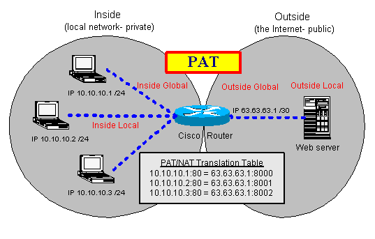
PAT is commonly known as “NAT overload” (or sometimes just “overload”). In this configuration, you have multiple clients on your inside network wanting to access an outside network (usually the Internet). You have few public IP addresses, many more than the number of clients, so you have to “overload” that real Internet IP address. In other words, you are mapping many inside clients to a single Internet IP address (many to one). For an illustration of PAT, see Figure as follows.
PAT.gif 
Pooled NAT
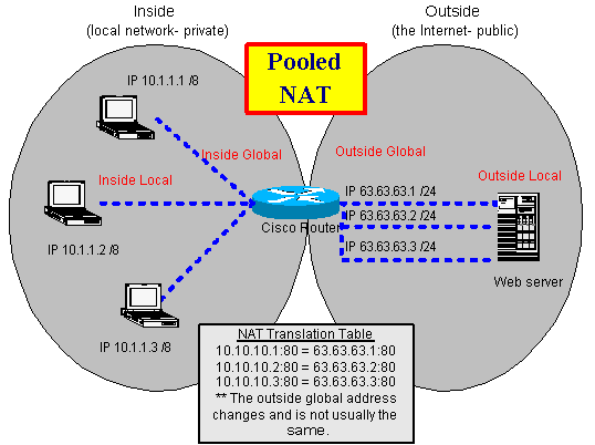
Pooled NAT is similar to PAT except you have the luxury of having a one-to-one mapping of addresses. In other words, you have just as many inside network clients as you do outside network IP addresses. You tell the NAT router the pool of IP addresses that are available, and each client receives its own IP addresses when it requests a NAT translation. The client does not get the same address each time it requests a translation; it merely gets the next available address from the pool. In the article "Set up NAT using the Cisco IOS", which explained how to configure Pooled NAT. For an illustration of Pooled NAT, see the following Figure.
how-to-configure-Pooled-NAT.gif 
Static NAT
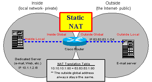
Static NAT is the simplest form of NAT. The most likely example is a mail server on the inside of a private network. The private network connects to the public Internet. In between the two networks, a router performs NAT. For a dedicated server, like a mail server, you would want a static (not changing) IP address. This way, every time someone on the Internet sends e-mail to the mail server, that server has the same public IP address. For an illustration of Static NAT
Static-NAT.gif 
You can perform a variety of functions with these three configurations. For the purpose of this article, we will focus on configuring PAT.

Configuring PATTo configure PAT/NAT correctly the first time, you need to understand the Cisco NAT terminology and how your IP networks/addresses map to each of the entities listed below:
  • Inside Local—This is the local IP address of a private host on your network (e.g., a workstation's IP address).
  • Inside Global—This is the public IP address that the outside network sees as the IP address of your local host.
  • Outside Local—This is the local IP address from the private network, which your local host sees as the IP address of the remote host.
  • Outside Global—This is the public IP address of the remote host (e.g., the IP address of the remote Web server that a workstation is connecting to).

You'll configure your Cisco router using seven commands. Let's assume that your Internet service provider gave you a 30-bit network containing two public IP addresses. This configuration would allow one address for your router and one address for your internal clients and devices. The first command you'll execute will tell the router which public IP address you want to use for PAT:
ip nat pool mypool 63.63.63.2 63.63.63.2 prefix 30

This command configures a pool (range) of IP addresses to use for your translation. In this case, we want only one address in our pool, which we will overload. We do this by assigning the same IP address (63.63.63.2) for the start and end of the pool.

The next command will tell your router which IP addresses it is allowed to translate:
access-list 1 permit 10.10.10.0 0.0.0.255

It's not a good idea to put “permit any” in the access list, even though you will occasionally see that as a recommendation in some sample configurations.

The next command is:
ip nat inside source list 1 pool mypool overload

This command puts the pool definition and the access list together. In other words, it tells the router what will be translated to what. The overload keyword turns this into a PAT configuration. If you left out overload, you would be able to translate only one IP address at a time, so only one client could use the Internet at a time.

Next, you need to tell PAT/NAT what interfaces are the inside network and what interfaces are the outside network. Here's an example:
interface ethernet 0
ip nat inside
interface serial 0
ip nat outside

With these commands, your PAT configuration is finished. You have told the Cisco IOS you are translating your network A into a single IP address from network B, that network A is on the ethernet 0 interface and network B is on the serial 0 interface, and that you want to allow the inside network to overload the single IP address on the outside network.

Finally, verify that NAT works. This can be as simple as doing a ping command from your inside local host to an outside global host. If the ping succeeds, chances are you have everything configured correctly. You can also use the following Cisco IOS commands to confirm and troubleshoot:
show ip nat translations [verbose]
show ip nat statistics

With the translations command, you should see the translation that was created from your ping test. But watch out: The translations will disappear after their time-out expires. If you have configured overload, these time-outs are configurable by traffic type.

NOTE: You should now understand the differences between PAT, Pooled NAT, and Static NAT, and you should be able to do a basic PAT configuration with the Cisco IOS. For more information, check out the links below.

How to Set up NAT Using the Cisco IOS?

Network address translation (NAT) is one of those rare information technology buzzwords that do exactly what its name implies. In this case, it translates one network address into another network address. The most popular use for NAT is to connect an internal network to the Internet. The proliferation of hosts that now connects to the Internet is causing a shortage of IP addresses, so NAT is a key tool for connecting corporate networks using private IP addresses to the Internet. Since Cisco provides the bulk of the routers that connects to the Internet, we’re going to show you how to set up NAT using the Cisco Internetwork Operating System (IOS).
Understanding NAT
Using NAT to connect to the Internet allows you to:
·Use only one public, registered IP address for Internet access for many thousands of private IP addresses at your site.
·Change Internet service providers (ISPs) easily, without readdressing the majority of hosts on your network.
·Hide the identity of hosts on your local network behind the single public IP address to keep outside hosts from easily targeting them.
The most difficult part of using NAT in the Cisco IOS is getting a handle on these four key terms:
·Inside LocalThis is the local IP address of the private host on your network (i.e., your PC’s IP address).
·Inside GlobalThis is the public, legal, registered IP address that the outside network sees as the IP address of your local host.
·Outside LocalThis is the local IP address from the private network, which your local host sees as the IP address of the remote host.
·Outside GlobalThis is the public, legal, registered IP address of the remote host (i.e., the IP address of the remote Web server that your PC is connecting to).
My first reaction after reading Cisco’s definitions for these terms was nearly total confusion, so don’t feel bad if you feel the same thing. But after seeing a diagram of these terms, it started to click for me. Take a look at Figure A for a logical diagram of these terms.
Figure A
Set up NAT using the Cisco IOS1
Configuring NAT
To configure the standard NAT scenario I mentioned in the opening paragraph, refer to Figure B and then look at the simple steps that need to be taken if you are using a Cisco router between your local network and the Internet.
Figure B
Set up NAT using the Cisco IOS2
·Configure your pool of legal, public IP addresses that the router can use to represent your local addresses on the Internet. This pool can contain as few as one or as many addresses as you would like to provide. For a small to medium-size network, one address is typically fine. The syntax is:
ip nat pool name start-ip end-ip {netmask netmask | prefix-length prefix-length}
·Define an access-list to specify what range of IP addresses is allowed to be translated from your local network to the remote network. This is, basically, a security feature asking you, “Who (what range of IP addresses) can use the NAT service?” The syntax is:
Access-list access-list-number permit source [source-wildcard]
·Specify that you want a dynamic translation from the source IP address to the pool and that you want to overload the pool address (or addresses). The syntax is:
ip nat inside source list access-list-number pool name overload
·Specify which of the router’s interfaces will be the “inside” address. The syntax for the Ethernet 0 interface is:
int en0
ip nat inside
·Specify which of the router’s interfaces will be the “outside” address. The syntax for the Serial 0 interface is:
int s0
ip nat outside
·Add a static route to your router to send any traffic not destined for your local network to the Internet interface. (In our case, I will use a default route to send traffic out the serial interface.) Here’s the syntax:
ip route 0.0.0.0 0.0.0.0 serial0
Listing A shows the resulting configuration for the router. One way to examine this on your router would be to issue the command show run.
ListingA
More Notes:
How is this Possible?
This configuration would allow any host on your local network (such as a desktop PC) to connect to the Internet using the single registered IP address that is being overloaded. Thus, any traffic from that local PC will have the source IP address of the router’s external interface.
If you think about this for a minute, you might wonder how multiple hosts can share the same IP address in the overload configuration, since we are taught that one IP address is assigned to one host and there is no sharing (any more than there is sharing of a social security number).
The answer to that question is that NAT gets around this rule by making an entry in a translation table for every host using a port. In this translation table, there is a map between the inside local, a port on the inside global, another port on the outside local and the outside global. By assigning these ports and keeping track of them in the table, the router is able to “overload” a single IP address with multiple hosts. This allows them to share a single IP address among them.

How to Configure NAT in Cisco IOS?

NAT (Network Address Translation), it in simple terms translates an IP address into another. Network Address Translation is of different types like
Static NAT (One to One)
Dynamic NAT (Many to Many)
Overloading (Many to One)
The main purpose of NAT is to hide the IP address (usually private) of a client in order to reserve the public address space. For example a complete network with 100 hosts can have 100 private IP addresses and still be visible to the outside world (internet) as a single IP address. Other benefits of NAT include security and economical usage of the IP address ranges at hand.
We will focus on Overloading form of NAT. This is called as Port Address Translation (PAT) or even Network Address Port Translation (NAPT). NAT Overloading translates many private IP addresses from a Local Area Network (LAN) onto a single registered legal Public IP address. Here, the source IP and the source port get translated to the Public IP and a different source port.
Typical network configuration would be on an Internet Router which enables all the hosts in the LAN to connect to the Internet using one single Public IP address.
The following procedure will help you to configure NAT Overload or Port Address Translation (PAT) in Cisco IOS:
NAT Inside Interface
Enable an interface on the router with an IP Address and mark it as nat inside interface. This is the interface that connects to your internal private network
WANRouter(config)# int fastethernet0/1
WANRouter(config-if)# ip address 192.168.1.1 255.255.255.0
WANRouter(config-if)# ip nat inside 
Enable NAT Outside Interface
WANRouter(config)# int serial0/0/0
WANRouter(config-if)# ip address 100.100.100.100 255.255.255.0
WANRouter(config-if)# ip nat outside

Configure NAT Pool
This will be a pool of legal Public IPs that is bought by the organisation. This could anything from one to many IP Address
WANRouter(config)# ip nat pool WANPOOL 100.100.100.10 100.100.100.10 netmask 255.255.255.0
This creates pool which has just one IP address. The syntax is
ip nat pool <pool name> startip endip {netmask netmask | prefix prefix-length}
Access List to Allow List of IP Addresses to NAT Translate
WANRouter(config)# ip access-list 10 permit 192.168.1.0 0.0.0.255
For more networks or hosts to overload the NAT pool simply add them to the access list
WANRouter(config)# ip access-list 10 permit 192.168.2.0 0.0.0.255
WANRouter(config)# ip access-list 10 permit 192.168.3.0 0.0.0.255
Instruct Router to NAT the Access list to the NATPool
WANRouter(config)# ip nat inside source list 10 pool WANPOOL overload
If this is an internet configuration then ensure that a default route on the IP to the outside IP address or outside interface
WANRouter(config)# ip route 0.0.0.0. 0.0.0.0 serial0/0/0
or
WANRouter(config)# ip route 0.0.0.0 0.0.0.0 100.100.100.100
Thats it. Job done!!!
The NAT setup is now complete.We have setup the router to translate LAN private IPs into the Internet public IPs.
To check the NAT status and statistics
WANRouter# show ip nat statistics
To see the active translations
WANRouter# show ip nat translations
We discussed NAT Overloading above: Cisco IOS NAT configuration. Here, we will configure a Static NAT on Cisco IOS Routers. Static NAT is rather straight forward as it is a one to one NATing between IP addresses as against the NAT Overloading or the Dynamic NAT where the IP addresses from the inside are NATed to a pool of IPs.

NAT Inside Interface
Enable an interface on the router with an IP Address and mark it as Nat inside interface. This is the interface that connects to your internal private network
WANRouter(config)# int fastethernet0/1
WANRouter(config-if)# ip address 192.168.1.1 255.255.255.0
WANRouter(config-if)# ip nat inside
Enable NAT Outside Interface
WANRouter(config)# int serial0/0/0
WANRouter(config-if)# ip address 100.100.100.100 255.255.255.0
WANRouter(config-if)# ip nat outside
Instruct Router to NAT the Source IP Address to that of a NATed IP.
WANRouter(config)# ip nat inside source static 10.1.1.11 172.1.1.11
WANRouter(config)# ip nat inside source static 10.1.1.12 172.1.1.12
WANRouter(config)# ip nat inside source static 10.1.1.13 172.1.1.13
Where 10.1.1.x IPs are NATed to 172.1.1.x
The syntax is
ip nat inside source static x.x.x.x y.y.y.y
That sets up the Static NATs. These can co-exist along with NAT Overloading or Dynamic NATs.
To Check the NAT Status and Statistics
WANRouter# show ip nat statistics
To See the Active Translations
WANRouter# show ip nat translations